Updated October 2026 · 9 min read
Most tolerance arguments we have with new customers start on the drawing, not on the machine. A dimension gets copied across from a machined brass part. Nobody questions it. The die is cut, the first samples land, and by then the unit price is fixed and there is only one plant left that can hold the number.
Zinc is forgiving in a way aluminium is not. It runs hot-chamber at a low melt temperature and fills fine detail, so most features on a well-designed Zamak part come out of the die at final size and never see a cutter. The skill is knowing which dimensions to leave alone, and which three or four are genuinely worth paying to machine.
Everything in this guide is published industry guidance rather than our house numbers: the International Zinc Association design rules, ASTM B86 and NADCA’s design pages. You can put the same table in front of any caster and compare answers. Where we think a drawing is heading for trouble, we say so before the die is cut.
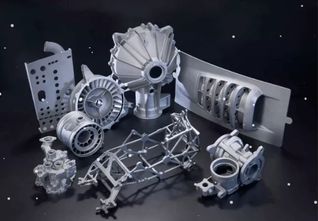
A tight tolerance is a purchasing decision, not a quality statement
People write ±0.05 mm on a drawing the way they write “stainless steel”. It feels like a statement about quality, but in practice it is a decision about money.
Whatever the die cannot hold has to be held afterwards, which means a fixture, a CNC pass, an inspection step and extra handling on every part for as long as the programme runs. The unit price climbs, and so does the list of plants that quietly drop out of the tender.
So the discipline runs the other way round. Let the process hold what it can hold naturally, and spend machining money only where function demands it. Sealing faces, bearing bores, threads and mating datums get machined. Decorative surfaces, locating features and structural ribs usually do not.
As-cast tolerance, and why the parting line ruins it
What an as-cast dimension actually measures comes down to where the feature sits in the die and how large the dimension is, and neither of those has much to do with how carefully the operator is watching the machine.
The first is where the dimension sits. Inside a single die half, the two steel surfaces that form the feature are fixed relative to each other. Across the parting line you are adding the tolerance of both halves plus the variation of die closing. Introduce a slide or a moving core and you add that movement as well. It is the difference between measuring a feature and measuring a machine.
The second is size, because tolerance widens as the dimension grows.
| Dimension formed in one die half | Published figure | Note |
|---|---|---|
| Linear tolerance up to 25 mm | ± 0.10 mm | Economic as-cast value |
| First-trial capability, new die | ≈ 0.2% of dimension + 0.10 mm | Expect this on first samples, not last |
| Machining allowance | 0.25 mm on top of casting tolerance | Must be shown on the drawing |
| Alloy 3 dimensional change with age | ≈ 0.0007 in/in | Only matters on press fits |
| Section ratio, thickest to thinnest | over 3:1 porosity risk, over 6:1 strength loss | Check every rib and boss junction |
Figures for Alloy 3 (Zamak 3, UNS Z33525) from IZA design rules rev. 2016, ASTM B86-23 and NADCA design guidance. Zamak 5 and the ZA alloys behave differently; the alloy data sits in our zinc alloy material information page.
There is a practical consequence here. Stop putting one general tolerance across the whole drawing. Mark the dimensions that run across the parting line or off a core, open them up, or move the datum onto a face you were going to machine anyway. Most European drawings we receive reference ISO 2768 for untoleranced dimensions, which is a reasonable default. If a feature needs better than ISO 2768, put it on the dimension. A general note will not carry it.
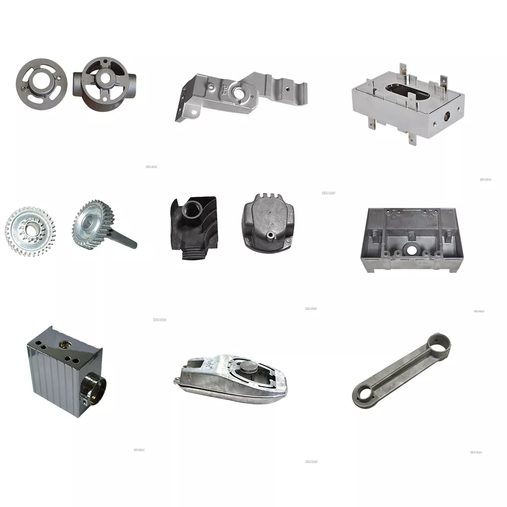
Wall thickness causes more scrap than anything else on the drawing
Wall thickness controls how the metal solidifies. Get it wrong and no amount of machine tuning will save the part, because porosity forms while the casting is still cooling.
Zinc fills thinner walls than any other die-casting alloy, and how thin depends mostly on how far the metal has to travel from the gate. Close to the ingate, sections can run below 0.5 mm. At a flow length around 200 mm, plan on up to 2 mm. By part size that works out at roughly 0.5 mm minimum on a small casting and 1.5 to 2.0 mm on a large one. There is no hard ceiling, but a typical zinc casting rarely goes past 6 mm, because thick sections cool slowly and gather shrinkage porosity.
Uniformity matters more than the minimum. IZA suggests an inscribed-sphere check: picture the largest ball that will fit inside each section of the part, then compare the diameters. A spread wider than 3:1 raises the porosity risk; beyond 6:1 you lose a meaningful amount of strength, and no amount of gating work will bring it back.
Parts converted from bar stock fail this check almost every time, because a machined shape has no reason at all to keep its walls even. Hollow the heavy sections out and put the stiffness back as ribs.
Draft angles, and the ribs everyone forgets
Every face parallel to the direction the die opens needs draft. How much depends on how hard the casting grips the steel.
Cored holes grip hardest, because the metal shrinks onto the core. Internal walls come next at 1° minimum. External walls need least, 0.5° minimum, since the part pulls away from them as it cools. Shallow ribs are the ones people forget, and they want 5° to 10° to release cleanly.
Zinc can hold zero draft on selected faces, which aluminium generally cannot. It costs extra die features to eject the part, so use it where it earns its place and agree it with your caster first.
Put the draft on the drawing as a general note, something like “draft 1° min. inside, 0.5° min. outside unless noted”. Then mark the faces that must stay square, and say whether those faces may be machined afterwards. If you leave that open, you will get a conversation instead of a quote.
Fillets, ribs and bosses
Fillet every inside corner, because fillets let metal turn a corner without turbulence, take the stress raisers out of the finished part, and make the die both cheaper to cut and slower to crack. For zinc, IZA puts the minimum at 0.4 mm and common practice at 1.6 mm on inside edges. Outside corners want a small radius too, since a sharp outside edge chips and sheds plating first. On a chrome lever that ends up in front of a customer, that is the failure mode you will hear about.
The parting line is the one edge normally left sharp.
Here is where neatly drawn parts usually go wrong. A generous fillet where a rib meets a wall adds local mass, and local mass is precisely where the inscribed-sphere check finds porosity. We have watched a 0.5 mm fillet radius on a rib junction turn into a rejection rate nobody could explain. And a solid boss is a thick section sitting in the middle of a thin wall. Core it out, keep its wall close to the nominal, and tie it to the nearest wall with ribs rather than a heavy base. If it takes a screw, name the screw type on the drawing.
Cored holes and cast threads
Small cored holes cannot go deep, and the limit rises fast with diameter.
| Cored hole | Blind depth limit | Note |
|---|---|---|
| 3 mm diameter | ≈ 9 mm | Cast a pilot, then drill to depth |
| 6 mm diameter | ≈ 45 mm | Covers most lock and hinge features |
| Over 10 mm diameter | A multiple of the diameter | Through holes go deeper than blind |
Thin cores are fragile and overheat, so a deep small hole is normally cast as a shallow pilot and drilled afterwards. On threads, external ones can be cast where the parting line splits them: 8 mm minimum diameter, 1 mm finest pitch, 8g the preferred fit, with 6e, 6g and 6h also achievable. Below that size, and on every internal thread, plan to tap or machine. Cast threads also carry a flash line at the parting plane, so a thread that has to gauge cleanly all the way round may still need a chase.
What the finishing line does to your dimensions
This is the part of the process that catches buyers who are used to ordering castings rather than finished parts. Three operations move metal, and all three are easy to forget at the drawing stage.
CNC machining brings spindles, bores, sealing faces and threads into the sub-0.05 mm range, depending on the feature and the fixture. Leave the 0.25 mm allowance and mark the face. Our CNC machining workshop runs in the same plant as the casting cell, which means one team owns the datum scheme from die to finished part instead of two.

Polishing removes material, and on a mirror finish for something like a lever handle the amount taken off is easily enough to matter on a tight dimension, so state which features have to survive polishing at final size. The same applies to the polishing line if the finish is decorative rather than functional.
Plating and PVD deposit metal on top. As-plated dimensions are larger than as-cast dimensions, which is where threads and press fits go wrong. Specify the dimension you need after plating, and let the surface treatment team control the pre-plate size. Corrosion performance on a bathroom or exterior part is decided at this stage, not in the die.
What shows up two years into production
Zinc Alloy 3 shrinks slowly as it ages, by roughly 0.0007 in/in, with a small loss of tensile strength and hardness over the years. On a tight press fit, ask whether parts should be stabilised before final machining. We have seen this turn up as a rattling spindle two years into a production run, which is an expensive way to learn it.
The second is temperature and load: zinc loses impact strength sharply below 0 °C, and it creeps under sustained load. If your part works outdoors in winter, or it is a clamp that stays loaded for years, aluminium is often the better material. Compare our aluminium die casting capability before you commit the die, not after.
What we want on the drawing before we quote
- The parting line, chosen at the widest section, in a single plane if the part allows. Everything else depends on which way the die opens.
- Even walls. If the part came from bar stock or brass, hollow the thick sections and bring walls toward one nominal thickness, using ribs for stiffness.
- Draft on every face parallel to the die opening, plus a list of the faces that must stay square.
- Fillets on inside corners, softened outside corners, sharp only at the parting line.
- A decision per hole: cast to size, cast a pilot and drill, or drill from solid.
- Tight tolerances moved onto a small number of machined faces and datums, with the machining stock shown.
- The alloy called out by standard, for example “Alloy 3 (Zamak 3) per ASTM B86”.
- Pre-plate or post-plate dimensions on anything the coating will move.
- Raised lettering and logos rather than engraved. Raised text is cut into the die, so it is cheaper to make and cheaper to change.
- Annual volume and a target unit cost, so we can pick the right number of cavities and the right level of automation.
Send those ten items and you will get DFM notes with the price. Send a 3D model and nothing else and you will get a price, then three weeks of questions.
Frequently asked questions
What minimum wall thickness can zinc die casting hold?
Close to the gate, sections can run below 0.5 mm. At around 200 mm of flow length, plan on up to about 2 mm. By part size, roughly 0.5 mm minimum on a small casting and 1.5 to 2.0 mm on a large one. Uniformity matters more than the absolute figure, so keep section ratios under 3:1.
What is the as-cast linear tolerance for a zinc die casting?
For a dimension formed inside a single die half, the economic as-cast tolerance starts at ± 0.10 mm up to 25 mm and widens as the dimension grows. Expect roughly 0.2% of the dimension plus 0.10 mm on first trial. Dimensions across the parting line or formed by a core are always looser.
Can a zinc die casting have zero draft?
On selected faces, yes. Zinc holds zero draft better than any other die-casting alloy, but it needs extra die features to release the part, so it costs tooling money. Keep it to the faces that truly need it.
Should I cast threads or tap them?
Tap internal threads and all small threads. Large external threads can be cast where the parting line splits them, at 8 mm minimum diameter and 1 mm finest pitch, but a thread that must gauge cleanly all round may still need a chase afterwards.
Why not cast the part exactly as it is machined?
A machined shape usually has uneven sections, square walls and sharp inside corners. Cast as drawn, it traps porosity, sticks in the die and cracks at the corners. A short redesign before the die is cut removes most of that risk.
Send a drawing and get DFM notes back with the price
STK has spent 20 years on precision zinc alloy die castings. Gravity casting, die casting, CNC, polishing, PVD, electroplating and painting all sit under one roof in Zhangzhou, China and Vietnam, which is why we can answer a tolerance question about a finished plated part rather than only about a raw casting. We hold ISO 9001 and run bathroom and door hardware programmes to German and US quality requirements, for brands including TOTO, KOHLER and Master.
Send the 2D and 3D drawing, the material and finish you want, and the volume you expect. If there is no 3D model, send a physical sample and we will build the model. Either way you get engineering comments next to the numbers, so you can see what a change on the drawing would do to the price.
- Request a zinc die casting quotation
- Zinc die casting services and the manufacturing capability page
- Equipment list
- Quality control, including CMM measurement and first-article inspection
- Assembly services if the programme includes sub-assembly
- Case studies and downloadable resources
Sources: International Zinc Association, Engineering Properties of Zinc Die Castings, Design Rules (rev. 2016); ASTM B86-23; NADCA Design guidance on draft, fillets, ribs and alloy selection. Figures are published design guidance and design-review starting points, not acceptance limits.